| BENDWAY WEIRS |
|
1. CATEGORY
1.0 – River Training
2. DESIGN STATUS
Level I
3. ALSO KNOWN AS
No other names known.
4. DESCRIPTION
Since 1988, Bendway Weirs have been tested by the US Army Corps of Engineers
Waterways Experiment Station (WES), and over 140 weirs have been built in
16 bends of the Mississippi River (Derrick, 1997b).
Since then, Bendway Weirs have been built throughout the United States, in various
stream systems, including California, Kansas, and Illinois.
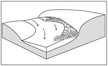
Bendway weirs are submerged,
upstream-angled stone sills (2,270 kg (5,000 lb) maximum weight stone), located
on outer banks, that are designed to control and redirect currents through
a bend and the immediate downstream thalweg crossing. Models and prototype
results indicate that the many benefits gained from the weirs may be applied
to the realm of small-stream bank protection as well (Derrick, 1997b).
The operating theory of Bendway Weirs is that flow can be captured and redirected by weirs at the upper end of a bend, controlled throughout the bend, and aimed in a direction perpendicular to the last weir in the bend. This theory has been essentially confirmed. In all bends with weirs, the thalweg of the stream is aimed perpendicular to the axis of the last weir of the set (Derrick, 1997b). The precision of aim is especially important in many narrow streams, and those with extremely short crossing lengths (Derrick, 1997b).
A minimum of five structures are typically placed in series (known as "weir
fields") along straight or convex bank lines where
flow lines are roughly parallel to the bank. Bendway weirs differ from
spurs in that they form a control system that captures and directs the streamflow
through the weir field, usually all the way through the bend (hence the name
Bendway Weirs).
5. PURPOSE
The main purpose of Bendway Weirs is thalweg management; that is, moving, realigning, or relocating the stream thalweg through and downstream of the weir field.
Bendway Weirs can reduce bank erosion by redirecting stream
currents through the vulnerable area; however, some bank scalloping will occur
between weirs, and the extent of this erosion is hard to predict (Derrick,
2002).
6. PLANNING
Useful for Erosion Processes:
Toe erosion with upper bank failure Scour of middle and upper banks by currents
Local scour Erosion of local lenses or layers of noncohesive sediment
Erosion by overbank runoff General bed degradation
Headcutting
Piping
Erosion by navigation waves
Erosion by wind waves
Erosion by ice and debris gouging General bank instability or susceptibility to mass slope failure
Spatial Application:
Instream Toe Midbank Top of Bank
Hydrologic / Geomorphic Setting.
Resistive Redirective Continuous Discontinuous Outer Bend Inner Bend Incision Lateral Migration Aggradation Conditions Where Practice Applies:
When considering the applicability of Bendway Weirs for a particular project, a careful assessment of the existing bend condition, geometry, planform, stages and discharges, sediment transport capacity, and stream features must be undertaken. The current directions and velocities entering the area of the proposed weir field must be carefully measured and analyzed. Weirs should be designed for the entire range of flow conditions, but with more emphasis on medium to high flows (Derrick, 1997b).
In a typical bend without Bendway Weirs, surface water currents tend to move toward the outer bank, and highest velocities occur along the outer bank of the bend, at least up to a very high flow condition. With the use of Bendway Weirs, water flowing over the weir is redirected at an angle perpendicular to the axis of the weir. Thus it is especially important to know the direction of water flow during expected flow regimes. The strong secondary currents in the bend are diminished. With the weirs angled upstream, it is theorized that flow is directed away from the outer bank of the bend, and pointed toward the point bar (inner part of the bend). Flow velocities within the weir field are significantly reduced, even with weir crests well submerged. For certain flow conditions, a set of weirs are designed to act as a system to capture, control, and redirect current directions and velocities through the bend and well into the downstream crossing. Emergent weirs act in the same manner as Spur Dikes (Derrick, 1997b).
Complexity:
Moderate to high. Flow direction and stage must be known.
Design Guidelines / Typical Drawings:
Reviews of design guidelines are provided by HEC-23 (Lagasse et al., 1997) and Biedenharn et al., 1998. Additional information about bendway weirs is available from the US Army Corps of Engineers Coastal and Hydraulics Lab Bendway Weir site (http://chl.wes.army.mil/research/hydstruc/bankprotect/bendweir/). Key design variables include crest angle, crest elevation, spacing, and length. Design also includes plan layout of groups ("fields") of structures along eroding banklines.Weir Angle: Bendway weirs most commonly have crest angles between 10°-20° pointing upstream from the bend radii (See typical drawing). However, the crest angle may vary from parallel to the bend radii (perpendicular to approach flow) to 20° upstream. The angle for the upstream weir (Weir 1) should be designed to capture and realign flow such that it correctly enters the remainder of the weir field. The downstream weir should be designed to direct flow into the first weir of the next weir field (if applicable), or to aim the current parallel to the downstream banks. Weirs can be used upstream of bridges to capture, turn, and aim the current through the bridge opening such that the flow is parallel to the banks at and downstream of the bridge (Derrick, 1997a).
Weir angle is very important. Physical movable-bed models of a reach of the Mississippi River showed that differences of 5° in weir angle had significant effects on the width and depth of the navigation channel (Derrick, 1997b).
Weir Spacing: Weir spacing should be determined by the radius of the bend, and the geometry and features of the outer (concave) bank of the bend. Typically, weir spacing should be about 1.5 times their length. Spacing decreases as bend radius decreases, so bendway weirs become less economically attractive in low-radius bends than in straighter reaches.
Weir Length: Bendway weirs are generally longer (1/3 1/2 stream width) and lower than spurs, and are designed to be continuously submerged or at least overtopped frequently. Weir length should be based on several factors, including: how far from the eroding bank the thalweg should be moved; the width of the water (percentage of cross-section) the weirs need to control to be effective; how erodible the point bars appear to be; and how much of the point bar can be safely eroded without detrimental side effects (Derrick, 1997a). Lagasse et. al., (2001) states that weirs longer than 1/3 stream width can alter channel patterns and impact the opposite bank.
Crest Width and Height: Crest width should be two to three times as great as the diameter of the largest stone (2-3 D100). Crest width may be wider when scour is anticipated.
The crest height is determined by the stage elevation of the design storm. Typically flows associated with annual high water will go over the weirs. It is important to remember that bendway weirs must be overtopped to work as designed. If the weirs are too high the flows will not be controlled in a predictable manner. Practitioners in Illinois and Kansas have had considerable success with very low (1 m or less) weirs.
Structures angled upstream redirect overtopping flow away from the protected bank (Biedenharn et al., 1998). Weirs placed on sand beds devoid of gravel may subside as sand is washed from beneath the stone (Shields et al., 1995); this problem may be addressed by placing filter fabric or a filter layer of finer stone underneath the stone spur. Alternatively, self-launching stone may be used; this will automatically stabilize the toe of the structure in any scour holes that form. Where additional scour is anticipated, more stone may be added to widen the weir crest. In this way, stone may be sacrificed without modifying the crest elevation.
Rock Gradation and Shape: When possible, bendway weirs should be constructed with graded (self-launching) stone. Self-launching stone will automatically stabilize the toe of the structure in any scour holes that form. Where additional scour is anticipated, more stone may be added to widen the weir crest. In this way stone may be sacrificed without modifying the crest elevation. The Corps of Engineers has stone gradations for Class A, Class B, and Class C rock (see Special Topic: Self-Launching Stone). Weirs and vanes placed on sand beds devoid of gravel may subside as sand is washed from beneath the stone (Shields et al., 1995); this problem may be addressed by placing filter fabric or a filter layer of finer stone underneath the stone spur.
In sand-bed and gravel-bed streams in Kansas bendway weirs have been built without the use of underlying filter fabric or stone footers. In these situations additional rock, intended to self-launch, is incorporated into the design. The additional rock is provided by making the weir crests wider and lower with a much wider ‘footprint’ (2 to 4 m). The wider crests reduce the chance that the crest elevation will be affected if rock is ‘launched’. Vanes and bendway weirs designed with low and wide crests, constructed with very poorly sorted rock (Figures 3 and 4), seem to reduce the potential for scour in sand-bed streams (Phil Balch, personal communication, 2002). In very sandy-bottomed streams, it is advantageous to build vanes using “shot rock” or well-graded stone that includes fines, as they prevent ‘through-flow’ of sand, and subsequent scour.
Rock Size: The size of the rock will depend upon the stream size and shear stress. See comments below under “Hydraulic Loading” on rock sizing. Some state DOTs (or state resource agencies) have published guidelines for specifying rock size, density and durability.
Some additional things to keep in mind are that entrance conditions to the stream reach must be stable, or be stabilized during construction. The flow direction entering the weir field must be known in order to control it. There must be sufficient riparian buffer between the weirs and other structures along the stream corridor to allow for scalloping that may occur between weirs (Derrick, 2002).

7. ENVIRONMENTAL CONSIDERATIONS / BENEFITS
Bendway weirs and other spur-type structures create geometrically complex water/boundary
conditions that in degraded streams can mimic the stable substrate,
velocity shelter, and cover provided by large woody debris accumulations and
tree falls. They provide benthic and fish rearing habitat, as well as pools
for adult fish. Disturbance to terrestrial habitats is usually minimal because
little upper bank clearing is required. Bendway weirs create minimal interference
with existing overbank drainage patterns and riparian access to the waterway.
Sedimentation and erosion in response to structures is usually most rapid during
the first few high flow seasons following construction, and then typically
exhibits mild fluctuation about an equilibrium condition (Shields, 1995).
Bendway weir fields create stable scour holes
at the stream ends of weirs, deep pools between weirs, and pool-riffle regimes
that increase the diversity and complexity of the streambed habitat (Derrick,
1997b). However, all thalweg management techniques have the potential to eventually
simplify stream corridor habitats and eliminate habitats associated with active
channel migration.
8. HYDRAULIC LOADING
Flow direction is more important than shear or velocity when designing weir fields.
Permissible shear and velocity for Bendway weirs is related to the size of rock used in construction. Other factors, such as the angularity of the stone, the thickness of the layers of stone, and the angle at which the faces of the stone structure are constructed also come into play. Detailed guidance for sizing stone for bed and bank stabilization structures is beyond the scope of this guideline, and many approaches are available (see Special Topic: Designing Stone Structures). However, the Maynord (1995) equation gives a D50 stone size for an angular stone riprap revetment of 0.875 m (2.9 ft) if the near-bank vertically-averaged velocity is 3.5 m/s (11.5 ft/s), and flow depth = 1 m (3.3 ft), and stone is placed on a bank slope of 1V:1.5H. Use of riprap larger than this is unusual.
9. COMBINATION OPPORTUNITIES
Bendway weirs may be combined with Longitudinal
Stone Toe and woody vegetation on middle and upper banks. Volunteer
vegetation may be prolific in humid regions with adequate seed sources. Willows
or other flood tolerant woody vegetation are sometimes planted in high densities
between adjacent structures, and grass and forb mixtures may be planted to
stabilize the bank until the woody vegetation becomes well established.
"Woody debris naturally positioned downstream
of the mid-point of a Bendway Weir (rootball immediately downstream of the
weir, trunk perpendicular to the weir) within a weir field stayed in place
even with repeated out-of-bank flows . Woody debris was either
in this position when the project was constructed, or naturally moved into
this position," (Derrick, 1997b). Appropriately positioned and anchored
large woody debris structures should be a feature of future bendway weir projects
(Derrick, 1997b).
10. ADVANTAGES
Flow can be redirected and predicted (even downstream of the weir field).
Weirs work best under high-flow, high-energy conditions.
Flow is considered controlled within the weir field.
Weirs blend well with other bank protection methods.
Aquatic habitat is improved.
Weirs can be retrofitted after project completion to improve hydraulic performance.
Weirs break up strong secondary currents (helical flow) in the bend.
The outer bank can become an area of low velocities, deposition, and parallel flow.
The thalweg of the channel is moved away from the outside bend, and towards the center of the channel.
Costs are competitive or lower than traditional methods (Derrick, 1997a, 1997b, 2002).
11. LIMITATIONS
Bendway weirs become less economically attractive in low-radius bends than in straighter reaches, because spacing increases as bend radius decreases.
Bendway weirs are not recommended in narrow streams (width less than 15 m (50 ft)), and have not been tried in high-velocity, high-gradient stream systems.
The redirective effects of Bendway weirs are limited in cobble and gravel bed streams, due to the resistance of the bed material.
Entrance conditions to the project reach must be stable and not actively meandering.
There must be sufficient space between the weir and bank structures to be protected, as scalloping may occur between weirs (Derrick, 2002).
12. MATERIALS AND EQUIPMENT
Stone should either be self-launching or angular stone with no more than 30%
having a length greater than 2.5 times its thickness. No angular stone should
be longer than 3.5 times its thickness (Lagasse et al., 1997).
13. CONSTRUCTION / INSTALLATION
Protection of the existing riparian zone is critical; therefore, access and staging areas need to be carefully planned. Turbidity may be a significant problem during construction, therefore construction techniques which reduce turbidity shall be employed, such as: minimize disturbance, use tracked excavators, winches or hand labor, work during low-flow periods, use dewatering or stream diversion techniques, or use stream isolation techniques (McCullah, 2004).
Working from the top of the bank, dig the key way and fill with stone.
If crest width is adequate, drive a high-tracked dozer or end dump over the newly-formed key to dump further rock. Proceed riverward, dumping stone progressively further out, until the required length is attained.
Reshape the weir to the final height and width with a backhoe.
14. COST
On the Missouri River, construction costs for earth core dikes and hard points
varied from $220 to $750 per linear m of structure ($65 to $236 /ft) or
$33 to $308 per m ($10 to $94/ft) of bank line protected, in 1984 dollars.
This works out to $389 to $1,327 per linear m of structure ($115 to $418/ft)
or $58 to $545 per m ($18 to $166/ft) of bank line protected, in 2003 dollars.
Costs were reported of $443 per linear m ($135/ft) of structure or $249 per m ($76/ft) of bank protected, in 1995 dollars, which works out to $535 per linear m ($163/ft) of structure, or $302 per m ($92/ft) of bankline protected in 2003 dollars (Derrick, 1997a) . These costs included Bendway Weirs and associated stone, bank paving, seeding, and miscellaneous expenses.
On the Ninnescah River, Kansas, a total bank length of 762 m (2500 ft) was protected with 2 geotextile Vanes and 10 geotextile Bendway Weirs, at an average cost of $33.33/m ($10.10/ft) (P. Balch, personal communication, 2004).
15. MAINTENANCE / MONITORING
There are several indicators that a system of Bendway Weirs is working (Derrick, 2002):
• Failed material is not removed from base of eroded bank.
• Outer bank between weirs is stable and vegetated.
• Sediment is deposited on outer bank after high flow events.
• "Dogbone" shaped depositional patterns formed between midpoints of weirs at the upper end of a weir field.
• Typically, deeper pools are found between weirs at the lower end of a bend.
• Point bar is scoured, and at times a vertical face is scoured on the point bar (usually from mid-bend to the downstream end of the bend).
• In some cases, low elevation mud-flats are deposited between bank ends of weirs.
16. COMMON REASONS / CIRCUMSTANCES FOR FAILURE
Spurs placed on sand beds devoid of gravel may subside as sand is washed from beneath the stone (Shields et al., 1995). This problem may be addressed by placing filter fabric or a filter layer of finer stone underneath the stone spur. Alternatively, self-launching stone may be used; this will automatically stabilize the toe of the structure in any scour holes that form.
The following conditions have been documented to lead to bank erosion problems: weirs incorrectly angled near the downstream end of a bend; weirs in an area of high flow concentration; and high energy flows over the point bar impinging the outer bank near the downstream end of the bend (Derrick, 1997b). In the last case, Longitudinal Stone Toe, in appropriate amounts, placed between the weirs in the area of impingement would stabilize the bank.
17. CASE STUDIES AND EXAMPLES
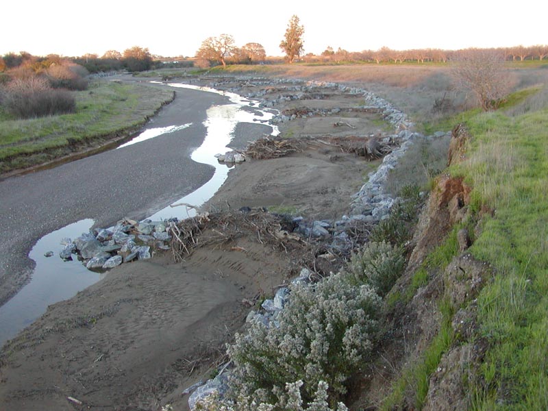
Scour was occurring on an outer bend of Cedar Creek in Northern California, which was causing serious erosion that had the potential to impact Highway 299. Riprap was used to armor the bank, and 9 bendway weirs were used to redirect flow away from the sensitive bank. Live stakes were installed at the toe, and willow posts were planted into and around all structures.
Buckeye Creek, Dunnigan Burn Dump, Yolo County,CA
McCullah and Hanford (1999) reported protection of a reach of bank along a small sand and gravel-bedded stream in northern California using bendway weirs combined with Longitudinal Stone Toe (LST). This project was for remediation of an abandoned burn dump. The bendway weir technique was chosen over rock-filled gabions because of the potential for habitat enhancement with the weirs. The extent of the fly ash (burn dump) was approximately 250 m however since bendway weirs need to start at a stable point the project length was extended to 700 m. The additional approximately 800 m of LST and 13 bendway weirs were constructed for 1/3 the cost (based on engineer's estimate) for 200 m of rock-filled gabions. The particulars are given in the table below. Minimal scour was observed at the ends of the structures, and significant deposition was observed within the weir field (see Table 1).
TABLE 1: Dimensions and Costs for Combined Bendway
Weir/Longitudinal Peaked Stone Toe Protection
(McCullah and Hanford, 1999)
Quantity |
SI units |
US units |
Length of protected bankline |
700 m |
2300 ft |
Height of
longitudinal stone toe protection |
1.1 m |
3.5 ft |
Total cost |
$200,000 |
$200,000 |
Cost per unit length of bank protected |
$285/m |
$87/ft |
Number of bendway weirs |
11 |
11 |
Length of weirs (not including tiebacks) |
17 m |
55 ft |
Height of weirs |
0.9 m |
3 ft |
Crest width |
0.6 m |
2 ft |
Stone required for weirs |
5 t/m |
1.5 T/ft |
 |
 |
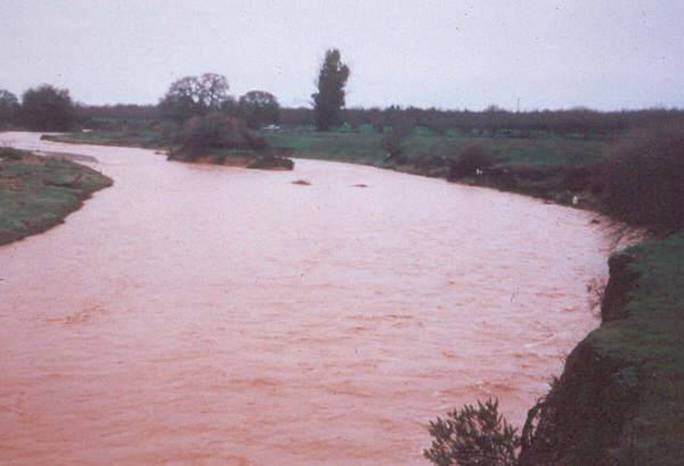
High Flows, Buckeye Creek, Yolo, CA |
|
 |
 |
|
|
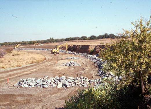
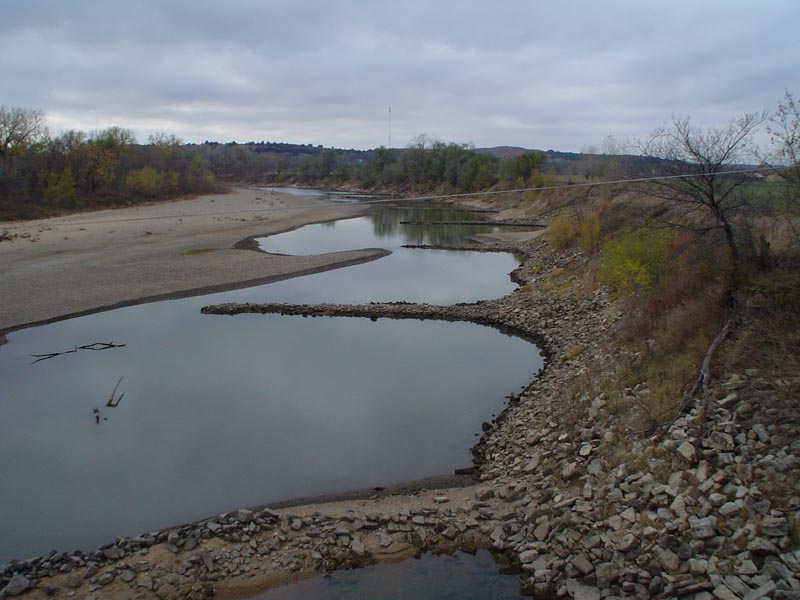
Kansas Bendway Weirs |
|
 |
 |
| Bendway weirs built with wide-crest and toe to reduce downstream scour.
Kansas, 2002. |
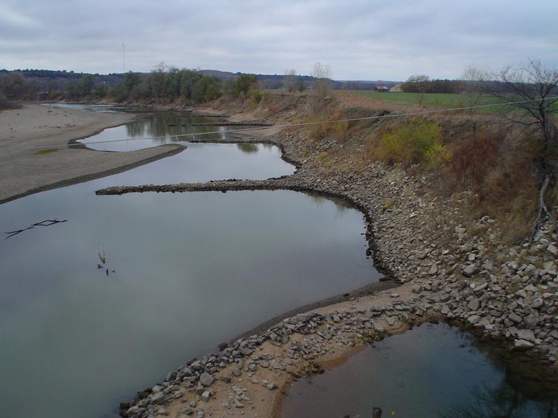
Wide crested bendway weir constructed with poorly sorted "shot
rock". Kansas, 2002. |
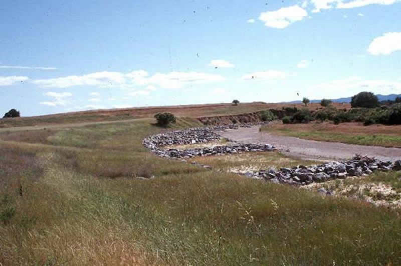
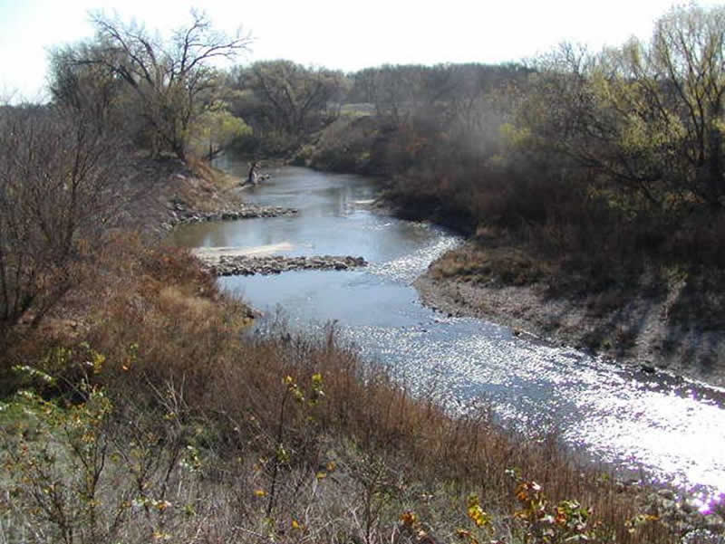
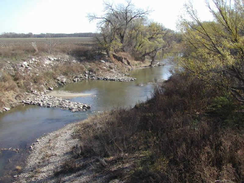
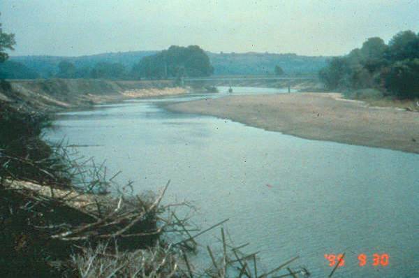
Barnes Road Bridge, Big Blue River, near Manahattan, Kansas.
This project was built in 1995. The eroding banks measured 35 ft high and the outer bank had eroded 75 to 100 ft during a flood in 1993 which also "failed" the downstream bridge. The bank migration circumvented the bridge abutment. The highway bridge required lengthening and repairs costing over $300,000 (Phil Balch, personal communication, 2004).
 |
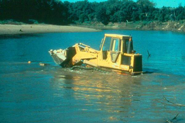 |
|
The weirs were built from the bank streamward during base flow conditions. |
 |
 |
|
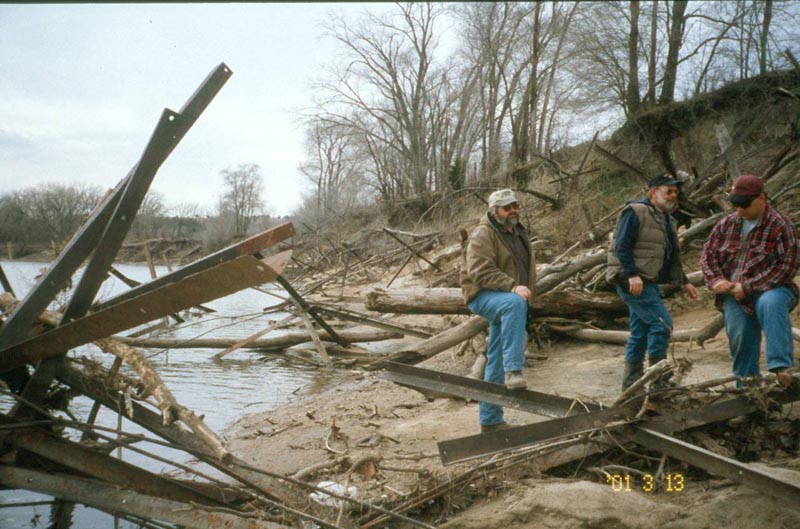
The effectiveness of Kellner Jacks is dependant on high sediment loads. The upstream Tuttle Creek Reservoir suppressed sediment loads which eventually “failed” the Kellner jack field. J. McCullah |
 |
 |
|
|
 |
|
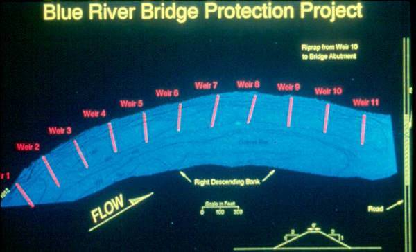
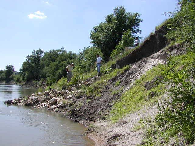
There are 11 Bendway Weirs, spaced 215 ft apart. The bank
rock goes from Weir 10 (DS 400 ft) to the bridge, and rock is up to the
10 yr flood event. There is no other rock on the bank except for the keys,
which are buried. This river is a navigable river by law for pleasure,
therefore the weirs are designed to be 2 ft under the base-flow water elevation. |
|
Please visit the Photo Gallery for
more pictures.
18. RESEARCH OPPORTUNITIES
More quantitative procedures are needed to select bendway weir design parameters based on site hydraulics and hydrology.
19. REFERENCES
Biedenharn, D. S., Elliott, C. M., & Watson, C. C. (1998). Streambank
stabilization handbook. Veri-Tech, Inc., Vicksburg, MS, CD-ROM.
Derrick, D. L. (1997a). Bendway Weirs Redirect River Flow to Protect Highway Bridge Abutments. Proceedings of the Second Symposium on Practical Solutions for Bridge Strengthening and Rehabilitation, Kansas, MO.
Derrick, D. L. (1997b). Harland Creek Bendway Weir/Willow Post Bank Stabilization Demonstration Project. Proceedings of the Conference on Management of the Landscapes Disturbed by Channel Incision, Oxford, MS.
Derrick, D. L. (2002). Course Notes for Stream Investigation, Stabilization and Design Workshop (with an emphasis on innovative approaches to streambank stabilization and restoration), San Jose, CA.
Lagasse, P. F., Byars, M. S., Zevenbergen, L. W. & Clopper, P. E. (1997). Bridge scour and stream instability countermeasures: Experience, selection and design guidance. (Hydraulic Engineering Circular No. 23, FHWA HI 97-030), Washington, D. C., pp. 1.3-1.11. (pdf) (2001 pdf)
Maynord, S. T. (1995). Corps riprap design guidance for channel protection. In C. R. Thorne, S. R. Abt, F. B. J. Barends, S. T. Maynord, and K. W. Pilarczyk. (eds.). River, coastal and shoreline protection: erosion control using riprap and armourstone. John Wiley & Sons, Ltd., Chichester, U. K., 41-42.
McCullah, J. A. (2004). Erosion Draw 5.0 - Erosion and Sediment Control Manual
with Typical Drawing Files for Computer-Aided Drafting, Salix Applied Earthcare,
Redding, California
McCullah, J. A., & Hanford, D. (1999) Bendway Weirs and Soil Bioengineering
for California Burn Dump Remediation. Salix Applied Earthcare Publication.
Shields, F. D., Jr., (1995). Fate of Lower Mississippi River habitats
associated with river training dikes. Aquatic conservation: Marine
and freshwater ecosystems 5:97-108. (pdf)
Shields, F. D., Jr., Cooper, C. M., & Knight, S. S. (1995). Experiment
in Stream Restoration. Journal of Hydraulic Engineering. 121(6): 494-502.
(pdf)
