| SLOPE DRAIN |
 |
| SLOPE DRAIN |
|
1. CATEGORY
4.0 – Slope Stabilization
2. DESIGN STATUS
Level II
3. ALSO KNOWN AS
Flexible down drain, pipe slope drain, chute.
4. DESCRIPTION
A slope drain is a drainage system used to collect and transport storm runoff down the face of a slope. This system usually consists of a berm at the top of the slope (or streambank) and a flexible pipe with end sections and outlet protection. A pipe slope drain is constructed with corrugated pipes (polymeric or metallic) and can be temporary or permanent. Curbs, berms or earthen dikes are used to direct runoff into a slope drain.
5. PURPOSE
A slope drain conveys concentrated runoff from the top to the bottom of a steep slope without causing erosion in transit. Concentrated overbank runoff can be a major cause of gully erosion, especially along deeply incised channels. Concentrated runoff discharged onto a slope can also contribute to the development of pore water and seepage pressures which can lead to mass slope failure. Slope drains are commonly used to: 1) temporarily convey runoff down the face of steep slope until permanent protection and/or cover can be established (Gray and Sotir, 1996), 2) prevent further cutting of a gully, and 3) serve as a permanent drainage-way down a steep slope where visual appearance is not a factor.
6. PLANNING
Useful for Erosion Processes:
Toe erosion with upper bank failure Scour of middle and upper banks by currents Local scour Erosion of local lenses or layers of noncohesive sediment Erosion by overbank runoff General bed degradation Headcutting Piping Erosion by navigation waves Erosion by wind waves Erosion by ice and debris gouging General bank instability or susceptibility to mass slope failure
Spatial Application:
Instream Toe Midbank Top of Bank
Hydrologic / Geomorphic Setting
Resistive Redirective Continuous Discontinuous Outer Bend Inner Bend Incision Lateral Migration Aggradation Conditions Where Practice Applies:
Slope drains, which are constructed from corrugated polyethylene pipe, are normally temporary measures that are used during grading operations until permanent drainage features are installed. Pipe drains are limited to a maximum drainage area of 2 ha (5 acres) per pipe and should be placed on stable slopes. Chutes are paved, open, permanent storm water conveyance structures that are generally used for larger drainage areas, viz., up to 15 ha (36 acres) per pipe.
Complexity:
Low to Moderate. Slope drains, particularly flexible polymeric pipe drains, are relatively simple to design and install. No heavy equipment is required and material requirements are minimal.
Design Guidelines / Typical Drawings:
Slope drains should be designed to collect and transport storm runoff from a two-year storm event. Important design considerations (Goldman et al., 1986) for pipe slope drains include the size of the pipe conduit, entrance section design, and outlet protection to prevent erosion/scour at the point of discharge. The pipe itself must be sized to convey the expected discharges. The accompanying table was developed by the USDA Natural Resources Conservation Service (1975) as a guide for sizing pipe slope drains in Maryland , where the annual rainfall is approximately 102 cm (40 in). The pipe dimensions for such drains should be calculated by a qualified engineer based on local conditions at actual project sites.
TABLE 1: Sizing Pipe Slope Drains
46 (18)
53 (21)
61 (24)
76 (30)
0.6 (1.5)
1.0 (2.5)
1.4 (3.5)
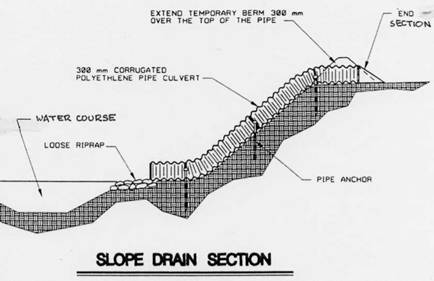
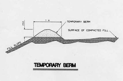
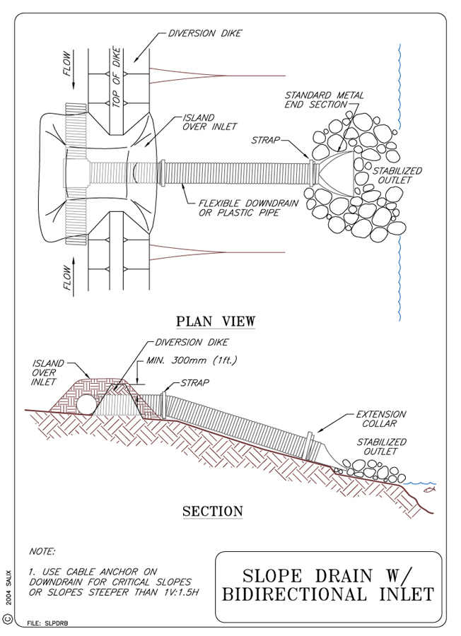
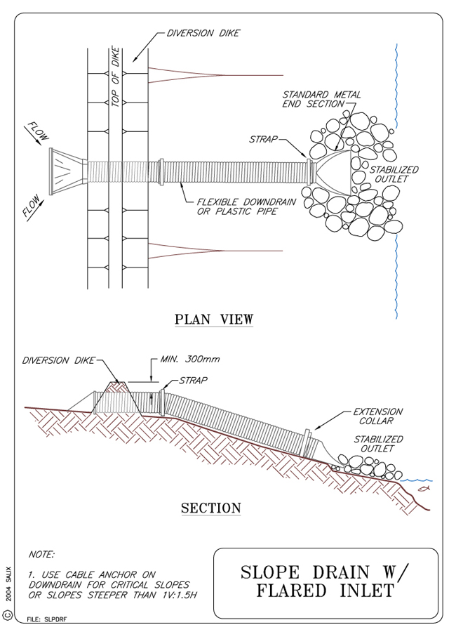
5.0 (2.0)The entrance to a slope drain must be designed and constructed with care. Slope drains should be constructed with berms that are not overtopped. At the pipe inlet, the top of the berm should be a minimum of 300 mm (12 in) higher than the top of the pipe. The entrance, or inlet, consists of a standard flared end section for culverts with minimum 15 cm (6 in) metal toe plate that is imbedded in the ground. This toe plate acts as a cutoff barrier that prevents runoff from undercutting the pipe inlet. A riprap apron can be used to protect the outlet. For a given pipe diameter (D), the apron should be 3D wide and 6D long, and it should consist of 15 cm (6 in) diameter stone placed at least 30 cm (12 in) deep. Outlet protection is essential because slope drains carry concentrated runoff. Additional construction specifications can be found in Goldman et al., (1986).
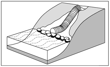
Figure 1. Schematic drawing of showing layout and placement of slope drain.
Figure 2. Schematic drawing showing typical dimensions of component parts of pipe slope drain
7. ENVIRONMENTAL CONSIDERATIONS / BENEFITS
Concentrated overbank runoff is one of the main causes of streambank degradation
and acts largely independent from lateral stream scour processes. Concentrated
discharge down a steep bank can cause headcutting and development of a gully
network that works its way back into the adjoining riparian corridor. This
gullying results in loss of soil and land behind the streambank crest. The
eroded soil is conveyed through the gully network and deposited as sediment
at the confluence of the mainstem gully and stream. Fine sediment can increase
turbidity in the stream and excessive deposition can destroy aquatic habitat.
A properly designed and constructed slope drain can prevent this sequence
of events.
8. HYDRAULIC LOADING
Pipe down drains used as temporary drainage measures are not intended nor
designed to resist stream flows during floods. Their main purpose and function
is to convey runoff down the stream during low flow periods. A pipe anchorage
system can be used to fasten the pipe securely to the slope and prevent pullout
or separation; however, this anchorage is not intended to resist hydraulic
drag forces from impinging streamflow. Some consideration must be given to
armoring pipe exit locations to prevent local scour.
9. COMBINATION OPPORTUNITIES
Slope drains are completely compatible with vegetative treatment of streambanks.
They can be used together effectively with either continuous or discontinuous
toe protection or armor. The latter provide protection against local scour
from concentrated pipe discharges. Slope drains can also be used in combination
with ditches and drains that intercept local overland flow and direct it
to the slope drain (see Technique: Diversion
Dike).
10. ADVANTAGES
Slope drains are visually relatively unobtrusive. Flexible down drains can
be placed and removed easily when used as a temporary drainage measure. Heavy
lifting equipment is not required and material requirements are minimal.
11. LIMITATIONS
Slope drains are likely to be torn or ripped from the bank during high flow
or flood events. A slope drain must be placed on a stable, relatively uniform
surface with a gradient not exceeding 1V:1H. If uncontrolled erosion occurs
in the drainage area behind the slope crest, the runoff may carry large amounts
of sediment. A slope drain can convey this sediment laden runoff directly into
an adjoining stream.
12. MATERIALS AND EQUIPMENT
The main material requirements for pipe slope drains are corrugated high density polyethylene (HDPE) pipes. Metal stakes and cable wire are normally used for anchoring or attaching the pipes to a slope. No heavy equipment is required for installation purposes.
13. CONSTRUCTION / INSTALLATION
Slope drains constructed from pipes are preferable to open chutes because water cannot spill out and erode the slope. The entrance section must be well entrenched and the conduit fastened securely to the slope to ensure that the drain functions as intended. If erosion is extensive, the drain itself may clog and lose a significant portion of its capacity. In these cases, sediment should be prevented from entering the drain by providing some type of inlet protection, e.g., either filter fabric, gravel & wire mesh, or block and gravel sediment barrier. Goldman et al. (1986) provide detailed guidance for the design and installation of these inlet protection systems. The following precautions should be observed when installing pipe slope drains:
Place slope drains on undisturbed or well compacted material at specified locations.
Hand tamp the soil under and around the inlet (entrance) in 150 mm (6 in) lifts.
Use water-tight fittings at all slope drain connections.
Secure pipe to slope at 3 m (10 ft) spacings.
Extend the drain beyond the toe of the slope and provide outlet protection.
Construct the berm 300 mm (12 in) above the top of the pipe at the pipe entrance.
Compact and stabilize the berm.
 |
 |
|
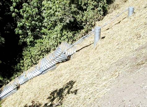
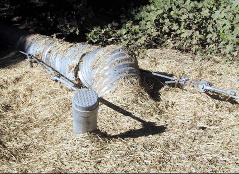
Figures 3 and 4. Photos of cable anchored pipe slope drain. |
|
14. COST
Costs for slope drains vary with the type and diameter of pipe used. Unit material costs for 375 mm to 750 mm (15 to 30 in) diameter unlined, corrugated high density polyethylene (HDPE) pipes vary from $10.50 to $27.90 per m ($3.20 to $8.50 per ft). A 750 mm (30 in) diameter corrugated, lined HDPE pipe costs approximately $44.25 per m ($13.50 per ft). Stone for apron and earthwork for slope and berm are additional cost factors, but likely site-specific, especially earthwork.
15. MAINTENANCE / MONITORING
Slope drains should be inspected weekly and after every rainfall event.
Any erosion of the slope, berm or outlet should be repaired immediately.
After the slope has been permanently stabilized and the permanent drainage
system is in place, the temporary slope drains may be removed. Clogged
drains should be flushed out or replaced.
16. COMMON REASONS / CIRCUMSTANCES FOR FAILURE
The most likely reasons for failure of slope drains include the following:
1. the pipes are sized incorrectly and are unable to conduct flows,
2. the berm is too low, and
3. pipes are clogged with debris and sediment.
Scour erosion at exit because of improper or inadequate exit protection against concentrated flow.
Detachment or separation of pipe because of inadequate anchorage or lateral movement during flood events.
17. CASE STUDIES AND EXAMPLES
Slope drains were used to protect the surface of a high, steep earthen highway
embankment supporting an interstate highway (I-275) near Johnson City, TN.
A straw mulch and hydroseed treatment provided adequate protection against
direct rainfall erosion but not against runoff generated by the road surface
prior to installation of curbing and permanent drains. The slope drains conveyed
this runoff safely to the base of the slope and prevented erosion generated
sediment from entering a watercourse located adjacent to the embankment toe.
The slope drains consisted of 225 mm (9 in) diameter, polymeric, corrugated
pipes spaced approximately 61 m (200 ft) along the slope as shown in the photos
below:
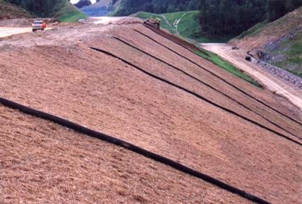 Figure 5. Corrugated pipe slope drains used to protect earthen highway embankment. |
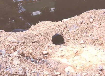 Figure 6. Berm and inlet for corrugated pipe slope drains shown in photo to left. |
18. RESEARCH OPPORTUNITIES
The conjunctive use of buried, flexible slope drains with Live Gully Fill
Repair. This approach would entail placing a flexible pipe drain on the gully
bottom, surrounding (encasing) it with a protective granular filter layer,
and then installing the Live Gully Fill repair on top of the buried slope drain.
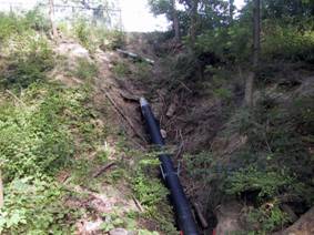
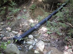
An example of such a solution is shown in the photos below, where a flexible,
corrugated pipe has been attached to a culvert discharge pipe located near
the top of a high streambank. The discharge from the culvert high on the slope
caused a major tributary gully to develop in the bank as shown in the photos.
The flexible slope drain now conveys this discharge safely to the stream channel
below and would permit the placement of a live gully fill repair atop the pipe.
(See Technique: Live
Gully Fill Repair)
|
|
Figure 7 and 8. Photos showing the use of a flexible pipe slope drain used to convey discharge from a culvert which had previously caused a large, tributary gully to develop in the streambank. |
|
19. REFERENCES
Goldman, S. J., Jackson, K., & Bursztynsky, T. A. (1986). Erosion
and sediment control handbook. McGraw Hill, New York.
Gray, D. H. & Sotir, R. (1996). Biotechnical and Soil
Bioengineering Slope Stabilization. John Wiley and Sons, New York, N.
Y.
USDA Natural Resources Conservation Service (1975). Standards and Specifications
for Soil Erosion and Sediment Control in Developing Areas, USDA, SCS,
College Park.